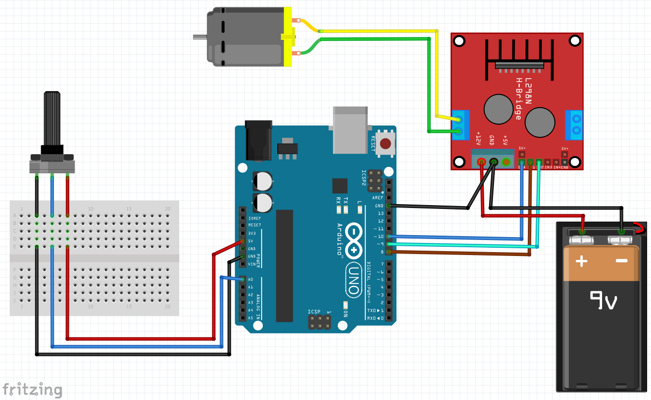
- #ARDUINO PWM WITH POTENTIOMETER HOW TO#
- #ARDUINO PWM WITH POTENTIOMETER MOD#
- #ARDUINO PWM WITH POTENTIOMETER SERIAL#
- #ARDUINO PWM WITH POTENTIOMETER FULL#
Additionally, Pict o Bl ox has the Set P WM pin () output as () block to set the P WM output on ev ive pins. ev ive also has 12 P WM pins ( 2 – 13 ) that can be used to control analog components.

In Arduino IDE, we use the P WM concept through the analog Write () function, which takes a value ranging from 0 to 255 and sets the duty cycle accordingly.
#ARDUINO PWM WITH POTENTIOMETER FULL#
It is a technique used to get analog results with digital means by using an on – off pattern to simulate volt ages between full – on and off.
#ARDUINO PWM WITH POTENTIOMETER MOD#
In conclusion, Pulse Width Mod ulation ( P WM ) is an effective way to use digital signals to control analog components such as motors. ExampleĬontrolling Pin 13 LED brightness using Potentiometer 2 in Arduino Mode:

You can select the pin using the drop-down menu.
#ARDUINO PWM WITH POTENTIOMETER HOW TO#
Int PotPin = A9 // Potentiometer connected to analog pin A9 OR how to generate a variable frequency PWM signal using Arduino Uno Arduino uno board contains an atmel. Int LEDPin = 13 // LED connected to digital pin 13 Of the potentiometer 1 of evive, the brightness of the LED is controlled. This code demonstrate the use of analogWrite(). Analog output pin that the LED3 is attached toNote that the values that analogRead() can take are from 0 to 1023, whereas those that analogWrite() can take are from 0 to 255. Analog output pin that the LED2 is attached to Analog output pin that the LED1 is attached to Analog input pin that the potentiometer is attached to The analog value from input pin can be rescaled into another value. We can connect the potentiometer's output pin to an ESP32's analog input pin, and then read the analog value from the pin. It will be similar to a volume meter or similar LED output showing how loud or how much power a device is using. The ESP32's analog input pin converts the voltage (between 0v and 3.3V) into integer values (between ), called ADC value or analog value. Then we will take the mapped value and use it to be able to tell what LED should currently be controlled by PWM. To accomplish this, instead of mapping the Analog Input to 0 to 255, we will map it to 0 to 765, or 3 times the width. wait 2 milliseconds before looping back to the topĪrduino-Uno-AnalogInOutSerial%20(1) 805×713 30.8 KBįor the expanded code, we will take and control 3 LED’s with PWM.

#ARDUINO PWM WITH POTENTIOMETER SERIAL#
print the results to the serial monitor Set the PWM of the output LED to the mapped value Variable set up to store the output to the PWM (analog output) Variable set up to store the value of the potentiometer. Starting Example Code //constants are used in this sketch to give names to the pins that do not change The sketch also uses the mapping function to take the analog input range (0 to 1023) and map it down to the analog output range (0 to 255).

Doing this with Old School Electronics In old school electronics this would be as simple as putting the LED in series with the potentiometer and connecting it to a voltage source. The potentiometer in this circuit will be used to control the Pulse Width Modulation(PWM) of the LED. The Arduino will take this readings on the connected analog pin and then software will use a PWM signal at the correct frequency to light the LED. This example shows how to use an analog input to control an analog output.


 0 kommentar(er)
